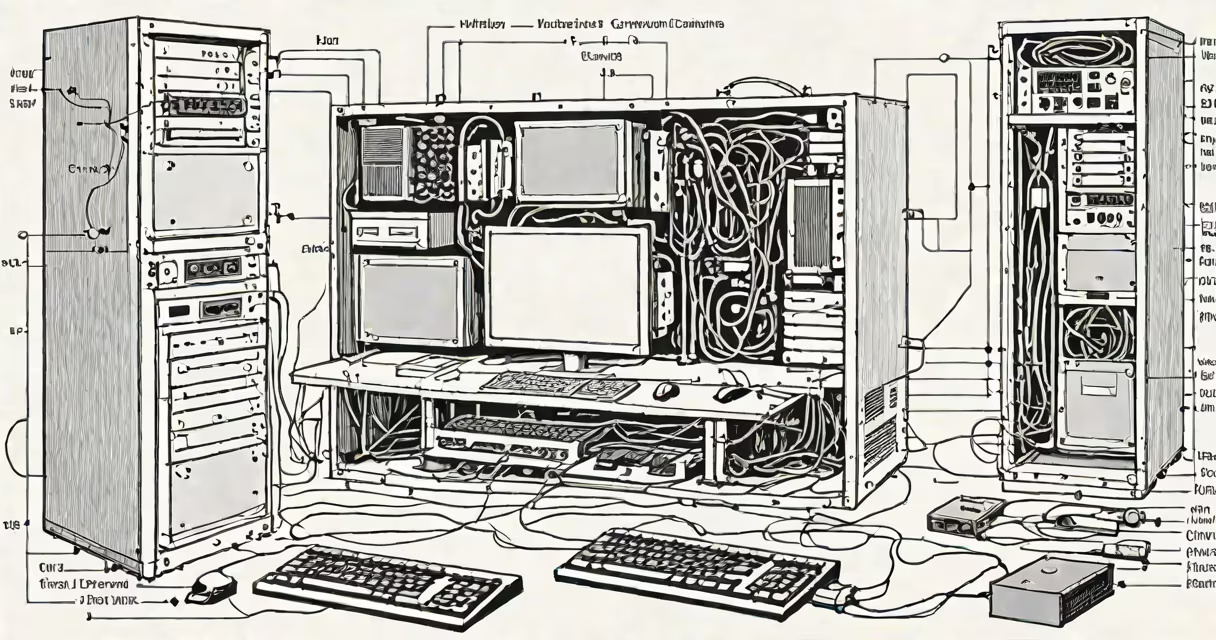
A drawing of computer system is a visual representation that shows the physical and logical components of a computing environment, including central processing units, memory modules, storage devices, input/output interfaces, and network connections, arranged to illustrate their relationships and data flow.
Such drawings serve as blueprints for engineers, educators, and developers. They depict how individual parts work together to process data, store information, and communicate. Unlike abstract diagrams, a drawing of computer system includes specific component shapes, connection lines, and often real-world proportions or standard symbols from electrical and systems engineering.
These illustrations are not just artistic renderings-they follow established conventions. For example, the CPU is typically shown as a square or rectangle with labeled pins, while memory modules appear as long rectangular blocks with staggered connectors. Data paths are drawn as arrows or lines indicating directionality, and buses are represented as parallel lines.
Each element in a drawing of computer system corresponds to a real function. The central processing unit (CPU) performs calculations and controls operations. Memory (RAM) holds data temporarily during active tasks. Storage devices like hard drives or SSDs retain data persistently. Input devices such as keyboards send signals; output devices like monitors display results.
Connections between components represent data or power flow. A bus-a shared communication pathway-may be shown as multiple parallel lines connecting the CPU to RAM and peripheral controllers. In more advanced drawings, layers indicate abstraction levels: the physical layer shows metal traces on circuit boards, while the logical layer displays data routing between processes.
For example, a drawing of a desktop computer system might show the motherboard as a central board with sockets for the CPU, RAM slots, SATA ports for drives, and USB headers. Peripheral devices like a mouse and keyboard connect via cables to USB ports. The power supply unit is shown with labeled voltage outputs. This structure allows someone to trace how electricity flows from the wall outlet through the PSU to the motherboard and then to active components.
Drawings vary based on purpose and audience. Engineers use detailed schematics with component part numbers and pin configurations. Students see simplified block diagrams that group functions into labeled boxes. Architects designing server rooms rely on floor plans showing rack positions, cooling units, and cabling routes.
| Type | Purpose | Detail Level | Example Use |
|---|---|---|---|
| Block Diagram | Conceptual overview | Low | Teaching basic system hierarchy |
| Schematic Diagram | Circuit-level design | High | Designing a custom motherboard |
| Network Topology | Data flow mapping | Moderate | Planning a corporate LAN setup |
| 3D Render | Visual presentation | High | Marketing materials for new PC models |
Block diagrams are common in textbooks. They use rectangles for major subsystems-CPU, GPU, RAM, storage-and arrows to show data movement. These are ideal for beginners who need to grasp the big picture without getting lost in technical details.
Schematic diagrams, used in electronics design, label every resistor, capacitor, and microcontroller. They include precise values and pin assignments. A single error in placement can prevent a system from booting. These drawings require specialized software like KiCad or Altium Designer.
One non-obvious fact: many drawings of computer system misrepresent data speed. Arrows in diagrams often look equal in size, suggesting uniform bandwidth. In reality, data transfer rates differ drastically-USB 3.0 moves 5 Gbps, while PCIe Gen 4 x16 reaches 16 GBps. A well-made drawing reflects these differences using thicker lines or annotations.
People often confuse a drawing of computer system with a flowchart or a mind map. A flowchart shows decision logic or process steps. A mind map organizes ideas hierarchically. But a drawing of computer system represents physical or logical interconnection in a functional environment.
Another mistake is assuming all system drawings are accurate. Some online images show a CPU connected directly to a monitor via HDMI-impossible without a GPU. Others place RAM inside the CPU socket, which violates physical architecture. Always verify component placements against official specifications.
I once reviewed a student's project submission that included a drawing of computer system where the GPU was drawn inside the CPU die. The image looked plausible at first glance, but upon inspection, the transistor count didn't match any known chip. The error stemmed from misunderstanding die stacking versus integrated graphics. Correcting it required cross-referencing Intel's and AMD's published die layouts.
Technical documentation, especially for industrial or embedded systems, relies heavily on drawings of computer system. When building a medical imaging device, engineers use these diagrams to ensure that sensors feed data correctly into the processor and that results are displayed accurately on a screen.
In education, they're essential for teaching computer science fundamentals. A high school course on digital systems might use a drawing of computer system to explain how the fetch-decode-execute cycle happens across the ALU, control unit, and registers.
For troubleshooting, technicians refer to system drawings to isolate faults. If a server fails to boot, checking the power delivery path in a schematic helps identify whether the issue lies in the PSU, motherboard, or CPU voltage regulator.
One notable example is the IBM System/360 manual from 1964. Its drawings of computer system were so detailed that they enabled engineers worldwide to build compatible machines. The clarity of those visuals contributed directly to the success of the platform.
Modern tools like Microsoft Visio, Lucidchart, and draw.io allow users to create accurate, shareable versions of computer system drawings. These platforms support standardized symbols from ISO/IEC 19752 and IEEE 310, ensuring consistency across teams and industries.
It also differs from an artificial intelligence computer system, which focuses on neural networks, training pipelines, and inference engines rather than hardware assembly. While both involve system architecture, AI systems emphasize data flow through layers of computation, not physical connections.
For instance, a drawing of a cloud-based AI system might show data centers linked by fiber-optic lines, with servers running machine learning models. The emphasis is on latency, data volume, and model distribution-not solder joints or voltage regulators.
Understanding the difference matters when selecting the right tool for your task. If you're designing a new laptop, use a 3D rendering with mechanical tolerances. If you're explaining how a web browser requests a page, use a flowchart with sequence arrows. Only a drawing of computer system captures both physical layout and functional interaction.
When creating or interpreting a drawing of computer system, always validate against real-world specs. Check manufacturer datasheets, official schematics, and industry standards. Accuracy prevents costly errors in development, deployment, and maintenance.
These drawings remain important in engineering, education, and product design. They translate complex interactions into accessible visuals. teaching students about system integration, a clear drawing of computer system delivers precision and insight.