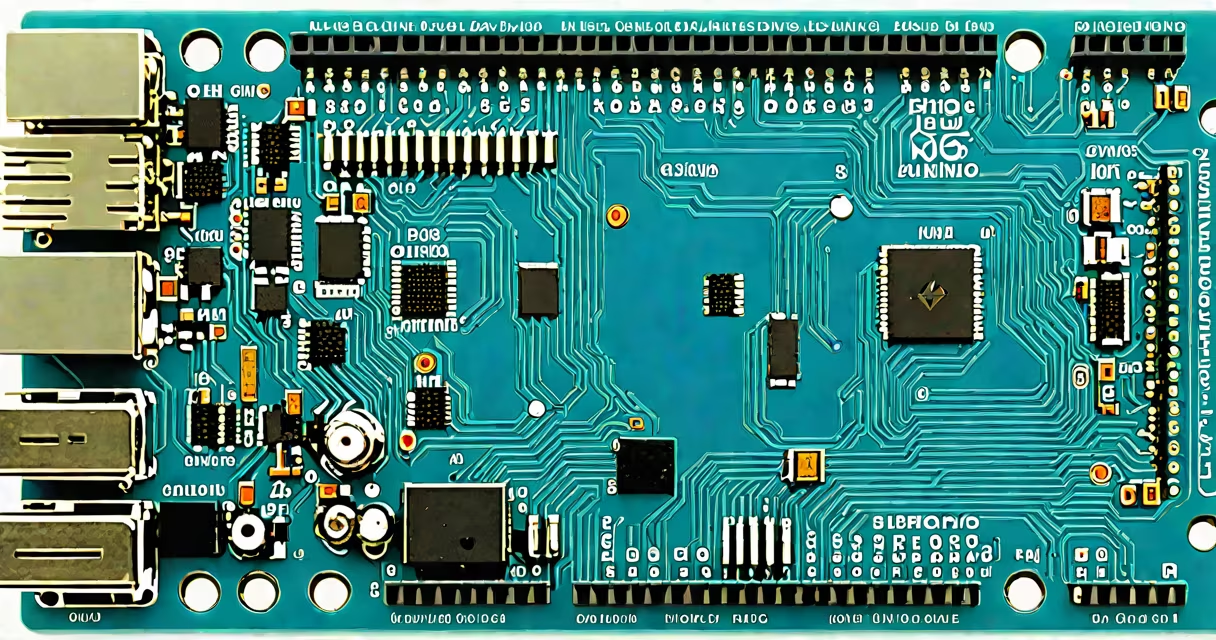
The Arduino Uno R3 pinout is a detailed map of all input/output, power, and communication interfaces on the board. It specifies the function, location, and electrical behavior of each of the 60 pins across 14 digital I/O, 6 analog input, and dedicated power and serial lines.
Understanding the pinout is essential for connecting external components like sensors, LEDs, motors, and displays. Without correct pin assignment, circuits fail to respond or damage the microcontroller.
Each pin has a specific role. For example, digital pin 13 controls the onboard LED, while analog pin A0 connects to the internal ADC for reading voltage levels from a potentiometer. Miswiring even one pin can prevent code from running or cause hardware failure.
The Arduino Uno R3 uses an ATmega328P microcontroller. This chip manages all pin functions through programmable registers and internal peripherals. When you write code using pinMode() or digitalWrite(), you're telling the microcontroller which physical pin to control and how.
Digital pins operate in two modes: input or output. Set as output, they can drive up to 40 mA of current, enough to light an LED or trigger a relay. Set as input, they read high (5V) or low (0V) signals. Internal pull-up resistors can be enabled via code to stabilize floating inputs.
Analog pins are not strictly for analog signals. They serve dual roles: as analog-to-digital converter (ADC) inputs and as digital I/O when needed. The ADC samples voltages between 0 and 5V and returns values from 0 to 1023, representing 10-bit resolution.
The board's 60 pins fall into five functional groups: digital I/O, analog inputs, power, serial communication, and special-purpose pins.
| Pin Type | Pins | Function | Use Case Example |
|---|---|---|---|
| Digital I/O | D0-D13 | General-purpose input/output. Support PWM on D3, D5, D6, D9, D10, D11. | Controlling a servo motor via PWM on D9. |
| Analog Input | A0-A5 | ADC inputs. Read voltages from 0-5V as 0-1023 integers. | Measuring temperature with a thermistor connected to A0. |
| Power | 3.3V, 5V, GND | Supply regulated voltage. 5V powers most shields; 3.3V for low-voltage sensors. | Connecting a 3.3V-compatible GPS module to the 3.3V rail. |
| Serial Communication | D0 (RX), D1 (TX) | Handle UART serial data. Used for debugging and interfacing with computers or other devices. | Using Serial.print() to send sensor readings to the Serial Monitor. |
| Special-Purpose | D2, D3, D4, D12, D13 | Support interrupts, SPI, I2C, and reset functions. | Using D2 as an interrupt pin to detect button presses instantly. |
Some pins have multiple roles. For example, D13 doubles as both a digital output and a status indicator for the onboard LED. Similarly, A0-A5 can be used as digital pins if needed, though their ADC functionality is lost.
The UNO R3 includes a 16 MHz crystal oscillator and a USB-to-serial converter (FTDI chip) that handles programming and serial communication. These components are not part of the ATmega328P itself but are critical to the board's operation.
Many beginners assume all analog pins are for analog sensors. But they can also be used as digital outputs. Setting pinMode(A0, OUTPUT) works just like setting pinMode(2, OUTPUT).
Another misconception: that the 5V pin supplies unlimited current. It does not. The onboard voltage regulator limits output to about 800 mA total across all 5V rails. Connecting a 12V fan directly to 5V will draw too much current and may burn out the regulator.
Also, the RX/TX LEDs only blink during serial transmission. They do not indicate general program execution. A blinking TX LED means data is being sent from the Arduino to the computer, not that the sketch is running.
One non-obvious fact: the RESET pin (pin 1) is pulled high by a 10kΩ resistor. To reset the board manually, connect it to GND briefly. This is useful for troubleshooting boot loops or stuck sketches.
Suppose you want to build a circuit that turns on an LED when ambient light drops below a threshold. You'll use:
A0 to read the analog voltage from a photoresistor (LDR).D13 to control the LED.5V and GND to power the LDR and LED.Wiring steps:
Code:
int ldrPin = A0;
int ledPin = 13;

void setup() {
  pinMode(ledPin, OUTPUT);
}

void loop() {
  int lightLevel = analogRead(ldrPin);
  if (lightLevel < 300) {
    digitalWrite(ledPin, HIGH);
  } else {
    digitalWrite(ledPin, LOW);
  }
  delay(100);
}
This code reads the LDR value every 100ms. If light level drops below 300 (roughly dark), the LED turns on. The pinout ensures correct signal routing and safe current handling.
I built this circuit during a workshop. The LED stayed off in daylight and lit up at dusk. The only issue was noise from the analog reading. Adding a 0.1µF capacitor between A0 and GND smoothed the signal. That's a detail often missed in tutorials.
Arduino provides a downloadable PDF of the official pinout layout at Arduino's official schematic. It shows every connection, including the FTDI chip, voltage regulators, and pin labels.
Always double-check pin numbers against the actual board. Some clones label pins incorrectly. The original Arduino Uno R3 has silkscreen printing matching the official pinout.
When in doubt, consult the datasheet for the ATmega328P. It details timing, current limits, and maximum operating conditions for each pin.
The Arduino Uno R3 pinout is not just a list-it's the foundation of every project. Mastering it prevents wiring errors, saves time, and enables reliable hardware integration.